The Driving Force in Laser Pulley Alignment
Alignment Condition Check
The misalignment conditions to be checked include vertical angularity, horizontal angularity and offset. The position of the transmitted laser line on the reflector indicates the vertical angularity and the offset. Horizontal angularity is indicated by the position of the reflected laser line on the transmitter.
Typical Machine Misalignment
| Vertical Angularity
|
Offset
|
Horizontal Angularity
|
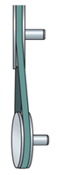
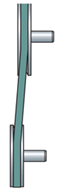
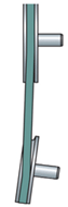
Misalignment Conditions as they are shown ON THE Pulley Pro® 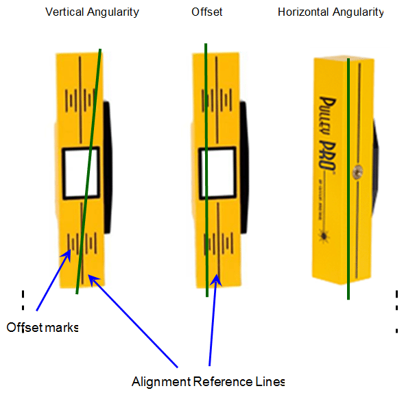
For different pulley edge thicknesses, use the offset marks on the face of the reflector to establish the amount of offset. The marks are in 1/8 inch increments.
Alignment processes should be carried out in an area protected from bright sunlight, or a shaded area in order to allow easy viewing of the laser line on the Pulley pro® units.
Correcting pulley misalignment
- Correct vertical angularity by shimming the moveable machine using precut 304 stainless steel shims. Correction of this angular misalignment can be observed on the reflector.
- Correct offset by adjusting the moveable pulley or machine axially. This correction can also be observed on the reflector unit.
- Correct horizontal angularity by adjusting machine laterally. This can be viewed transmitter during adjustment.
By following the three steps above, alignment of the belt drives should be completed quickly. However, one alignment correction may affect other alignment conditions, so the procedures above may need to be repeated until the system is completely aligned.
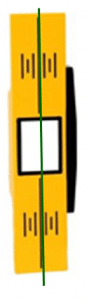
Good alignment is achieved when the transmitter laser line and the corresponding reflected laser line coincide with the reference lines on the reflector and laser transmitter respectively.
| Reflector
|
Source
|
Overhead
|

IMPORTANCE OF GOOD PULLEY ALIGNMENT
Good pulley alignment increases belt drive reliability and efficiency by reducing premature wear or failure of pulleys, belts and bearings. Pulleys can be aligned using conventional string and straight-edge methods, but this is often time consuming and prone to error.
Pulley pro® is a laser system specifically designed for the alignment of belt driven equipment. Patented and proven reflected laser beam technology significantly helps to reduce drive installation time, manpower and potential errors associated with pulley alignment and installation.
The Pulley pro® system uses a return beam angle that is twice the angle of incidence, so the reflected beam travels twice the distance, dramatically enhancing accuracy.
Alignment is indicated with great accuracy, resulting in labor savings and increased production uptime.
Machine Preparation
Before commencing any work ensure basic safety rules are adhered to.
Loose clothing or long hair must never be allowed anywhere near belt-driven machinery. All equipment MUST be locked out and tagged out.
Causes of belt failure
Before beginning any pulley alignment, causes of belt or pulley failure must be examined and corrected to prevent recurrence.
Causes of failure could include:
- Poor drive maintenance (wrong belt tension, pulley misalignment)
- Environmental factors (sunlight, harsh temperature fluctuations)
- Improper installation (wrong belts/sheaves, belts forced onto grooves),
- Operating factors (overload, shock load)
Inspection
Perform a visual inspection of the belts and of each pulley and its grooves. Look for and feel for cracks, chips, or excessive groove wear. Proper contact between the belts and the pulleys must be ensured.
Worn belts or pulleys and other components should be replaced before proceeding with pulley alignment.
Pulley Alignment
Soft Foot
Inspect the moveable machine for “soft foot”. Feeler gauges can be used under a loosened foot to measure the gap. Shim the machine foot with the largest amount of gap (the amount indicated with the feeler gauges) until no reading is larger than 0.05mm (0.002” or 2 mils).
Use precut 304 stainless steel shims. Severe “soft foot” distorts the machine frame when bolted down, causing damage to seals and bearings. It could also lead to high vibration levels on the machine bearings.
Drive Belts
The condition of the worn belt is a good indication of the type of misalignment or other problems that may be present. Belts must be changed as soon as undue wear is detected. For a multiple-belt drive, all belts must be replaced together. Only belts from the same manufacturer should be combined together in order for the belts to share the load equally.
In order to replace the belts on a belt drive system, they must first be loosened. This is often accomplished by simply loosening the driver or driven unit and reducing the center distance. In other cases, an idler pulley may need to be loosened and moved. Belts must never be forced or rolled onto a pulley as this can damage the pulley as well as the belt tensile cord.
New belts must be properly stored.
- They should be kept in a cool, dry place with no exposure to direct sunlight or heat.
- They also should not be hung from single pegs.
For further information, refer to “Belt Drive Preventative Maintenance & Safety Manual”.
Pulleys
If installing new pulleys and belts ensure that the correct-belt-pulley combination and the correct size belts have been selected. Existing pulleys should be inspected carefully for wear and replaced if necessary. Consult the “Belt Drive Preventative Maintenance & Safety Manual”.
PULLEY RUN-OUT
Axial pulley run out will influence alignment readings. Axial run out should be confirmed to be within recommended limits.
PULLEY & DRIVE BELT ALIGNMENT
There are three basic parameters that describe pulley misalignment. These include vertical angularity, horizontal angularity, and axial offset and may occur in any combination.
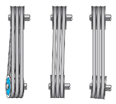
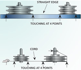
There are several pulley alignment setup methods.
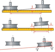
The most common is the straightedge and string method in which the strings must touch the two edges of each pulley face simultaneously (four-point contact for drives with two pulleys).
The pulleys should be rotated half a turn and checked again. Since a string can bend around corners, it is not easy differentiating between offset and horizontal angularity when only three-point contact is made. A straightedge or string also cannot always detect twist angle.
Straight Edge Method
 String Method
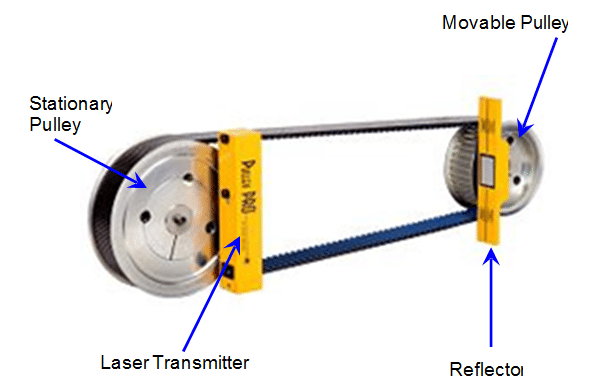
The Pulley pro® on the other hand mounts magnetically to the face of most pulleys.
It projects a laser line onto the reflector which is magnetically attached to the other pulley face. Alignment involves ensuring that the transmitted and reflected laser lines match with the respective reference lines.
The diagrams below depict misalignment conditions using the Pulley pro® and the corresponding corrections as observed on the units.
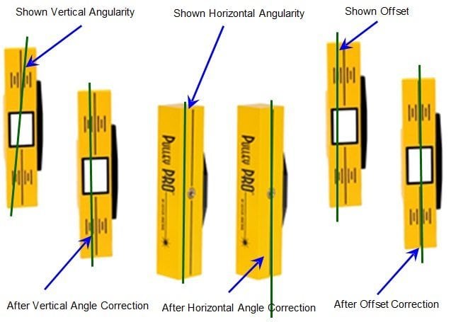
Vertical angularity should be corrected first. This is done by shimming the unit that the movable pulley is mounted to. The next step is to correct horizontal angularity.
This is accomplished by shifting or twisting the position of the unit that the movable pulley is mounted to. Use lateral jack-screws if available, otherwise the unit will need to be loosened and re-positioned. Finally, correct offset by moving the unit that the movable pulley is mounted to axially or re-position one of the pulleys on its shaft.
Since performing one alignment correction almost invariably affects the other alignment conditions, this process may have to be repeated several times.
The sequence in which the misalignment correction is carried out may vary from one situation to the next.