Note: Make sure that the roll surface is free of dirt and nicks, as this may affect your readings.
1. Mount the SX-5150T Laser Transmitter unit on the stationary or reference roll. Do this as follows:
a) Hook straps of adequate length on the left and right mounts of the back of the SX-5150T Transmitter Unit, and place the Transmitter Unit on the stationary roll so it faces the Roll To Be Moved (RTBM), and hold on to it! (See Figures 1 and 2)
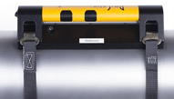 Figure 1 Figure 1 |
 Figure 2 Figure 2 |
b) Now bring the straps around the roll and hook them into the left and right mounts on the front side of the Transmitter Unit (See Figures 3 and 4).
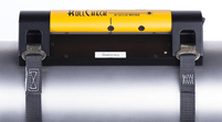 Figure 3 Figure 3 |
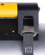 Figure 4 Figure 4 |
Try to wiggle the Transmitter Unit to make sure it is sitting tight and square on the roll. Use a feeler gauge (0.001”) to make sure that all points of the bracket are making full contact with the roll surface.
Tip: If you have a very delicate roll surface, place a plastic sheet of shim stock with a minimum thickness of 0.003” and the size of 6”x24” between the roll surface and the RollCheck.
This will protect the surface of the roll and will not affect your alignment.
2. Mount the SX-5150R Reflector unit on the Roll To Be Moved (RTBM). Do this as follows:
c) Hook straps of adequate length on the left and right mounts of the back of the SX-5150R Reflector Unit, and place the Reflector Unit on the Roll To Be Moved (RTBM), and hold on to it! (See Figures 5 and 6)
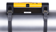 Figure 5 Figure 5 |
 Figure 6 Figure 6 |
d) Now bring the straps around the roll and hook them into the left and right mounts on the front side of the Reflector Unit (See Figures 7 and 8).
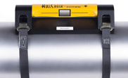 Figure 7 Figure 7 |
 Figure 8 Figure 8 |
3. Turn on the Transmitter Unit and observe where the Transmitter’s vertical laser line strikes the Reflector Unit. If necessary, rotate the Transmitter Unit to make the vertical laser line hit the vertical groove on the Reflector Unit that is located above and below the mirror in the center.
4. If you find that the vertical line does not coincide with this vertical groove of the Reflector unit, it will be necessary to slide the Reflector Unit sideways until it does coincide. Slide the Reflector Unit sideways on its roll as needed to make the transmitter vertical laser line hit the vertical groove on the Reflector Unit, re-secure the straps if necessary, making sure the Reflector Unit is tight to the roll.
5. Now observe where the Transmitter’s horizontal laser line strikes the Reflector Unit. If necessary, rotate the Transmitter Unit to make the horizontal laser line hits near the center of the front of the Reflector Unit.
6. Now rotate the Reflector Unit so as to position the horizontal groove directly on the Transmitters horizontal laser line.
7. Any vertical misalignment of the rolls will now be seen in that the Transmitter’s horizontal laser line does not coincide perfectly with the black horizontal groove in the center of the Reflector Unit. The laser line will be observed to be slightly high at one end and slightly low at the other. (See Figure 9)
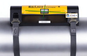
Figure 9
Note: Roll to be moved (RTBM) is not on the same plane as the stationary roll.
8. Now raise or lower one end of the Roll To Be Moved (RTBM) to make the horizontal laser line match with the black horizontal line on the Reflector Unit. When this is done, you have corrected the vertical angle or pitch that existed between the rolls. (See Figure 10)
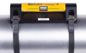

Figure 10
Note: Roll to be moved (RTBM) is now on the same plane as the stationary roll.
9. Now observe that the reflected vertical laser line is striking the Transmitter Unit. If necessary, rotate the Reflector Unit so as to cause the reflected vertical laser line to strike the Transmitter Unit through the center.
10. Observe if the reflected vertical line is aligned with the vertical black line of the Transmitter Unit. If it is not, you have horizontal angular misalignment (lack of parallel) between the rolls which must be corrected. (See Figure 11)
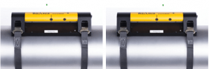
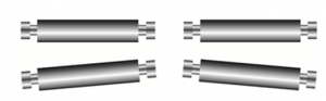
Figure 11
11. Move one end of the RTBM sideways as needed to cause the reflected vertical laser line to coincide exactly with the vertical groove in the center of the Transmitter Unit. Once they do, you have achieved parallel alignment of your rolls and your job is nearly finished. (See Figure 12.)
Note: The reflected horizontal laser line has no significance.
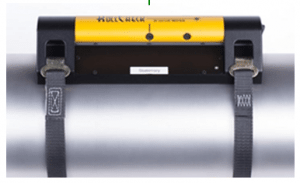

Figure 12
Note: Reflected laser line shows that the rolls are parallel to one another
12. Now remove the Transmitter and Reflector Units from both rolls.
Caution!! Be extremely careful to hold on to the Transmitter and Reflector Unit while removing the straps so they do not suddenly fall off of the roll!!!
13. Now remount the Transmitter and Reflector Units as described in Steps 1 through 6, and observe that the Transmitter horizontal laser line still coincides with the horizontal black line on the Reflector Unit, and that the reflected vertical laser line still coincides with the vertical black line on the Transmitter Unit. They should, and this is your confidence check that the units were properly mounted the first time around, and that you have done a good job of aligning your movable roll to your stationary reference roll.
Note: Remove all components and make certain that no loose parts are left behind anywhere in the work area.
Charging Instructions
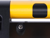
Note:The charging port is located on the back of the laser transmitter. |
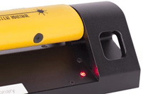
Note: The charging LED is located on the front of the laser transmitter. |
The RollCheck equipped with a rechargeable lithium ion battery with a run time from 16 to 20 hours continuous.
A red LED will indicate the status of the unit as it is charging.
When the charger is plugged into the transmitter, the red LED is illuminated until fully charged, the red LED will turn off when the battery finished charging.
Charging time about 5 hours.